MQTT – why it is worth to look at?

MQTT – why it is worth to look at?

Hi Readers,

mqttorg-glow

Today I would like to introduce you MQTT (MQ Telemetry Transport). I would also like to describe it’s benefits and why it is better then HTTP protocol in Internet of Things (IoT) world.

HTTP is mature and really established protocol. Is easy to use and know by almost everybody. Is perfect for request and response. But in our IoT world is not ideal. It is text based protocol which requires more bandwidth. Also requires working web server which requires small or bigger server but will not work on really small IoT devices. This could be a bit a limitation for users as web server and long text response and request will require more power which unfortunately for IoT uptime (battery )is crucial.

However MQTT is publish and subscribe (pattern) based light weight messaging protocol with quality of service. I think this already give us flexibility. In large scale systems which based on network with small end-devices being able to subscribe to one or another sensor without writing a parser sound really useful. It requires minimal bandwidth as it is binary format. It header is build from just two bytes. Which also shows that devices uses MQTT requires less battery.

In MQTT our central point is a broker which sends received messages publishes to subscribers. As simply like that:

push-mqtt-for-the-internet-of-things-7-638


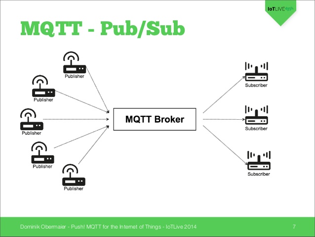
There are number of brokers but the one most is Mosquitto (mosquitto.org). It supports most of the platform and can be installed on almost any computer.


2013-11-02-comms_overview

If you would like to read more about mqtt protocol in more technical view you can read it here:

http://docs.oasis-open.org/mqtt/mqtt/v3.1.1/os/mqtt-v3.1.1-os.html


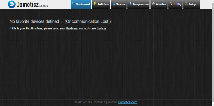
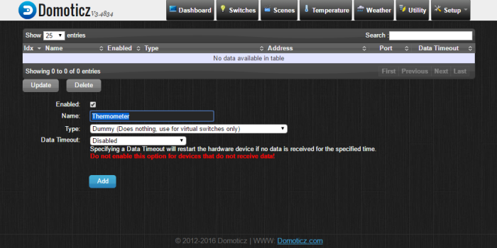
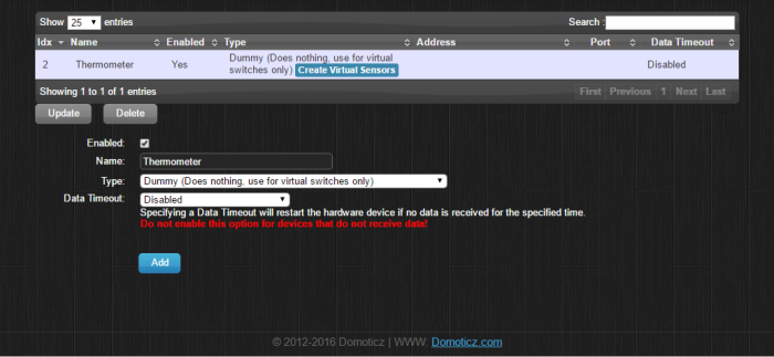
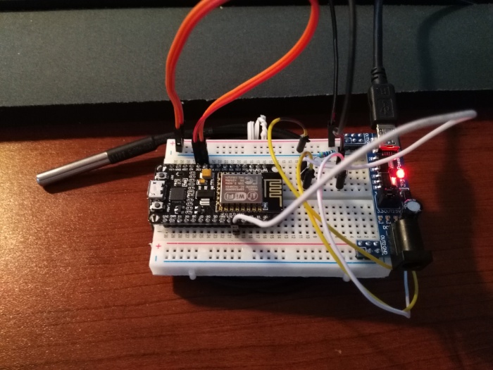
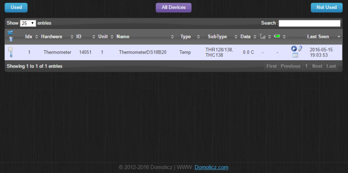
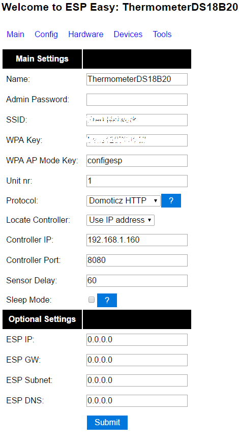
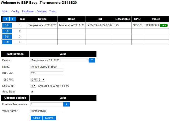
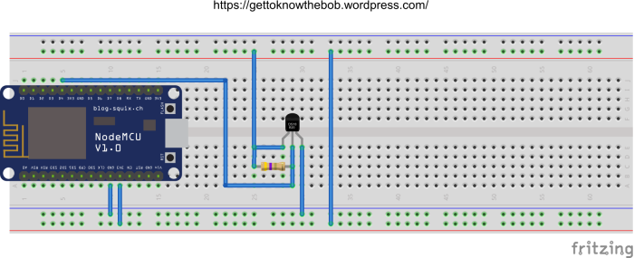
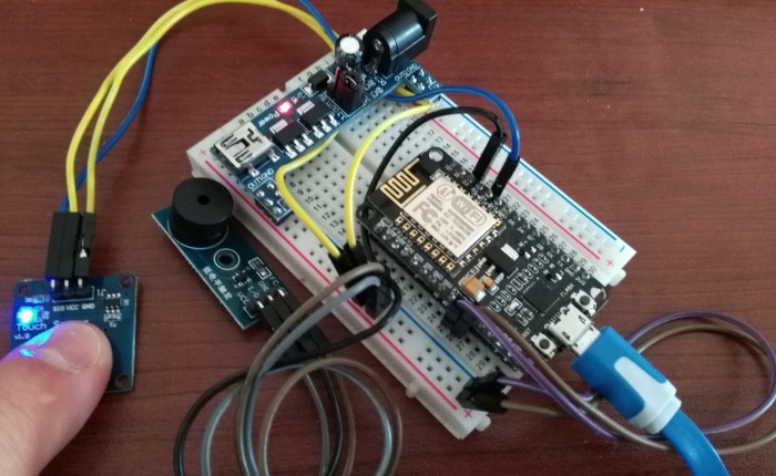
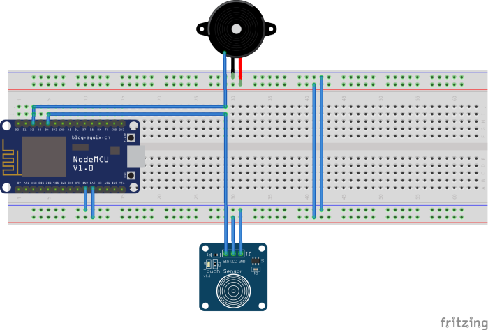
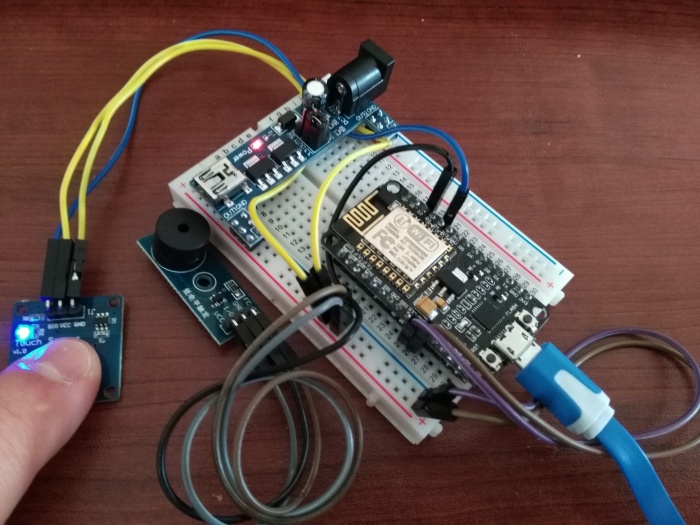
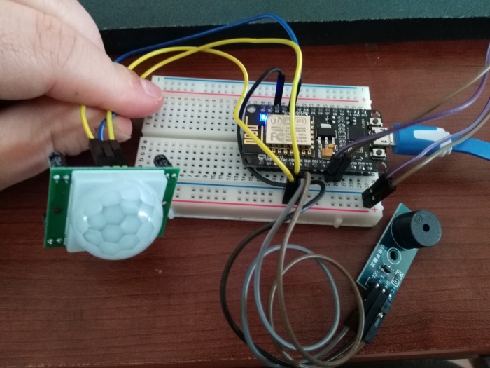
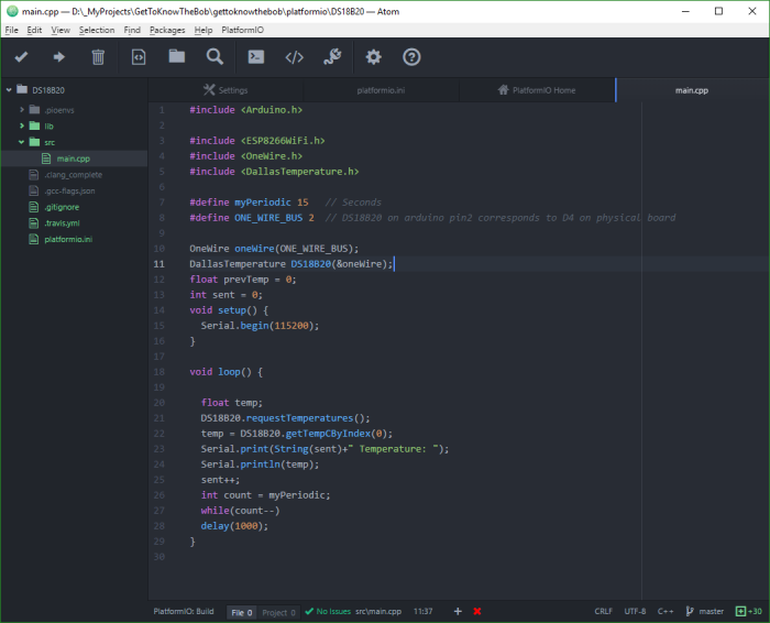
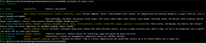
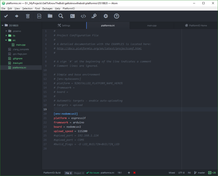
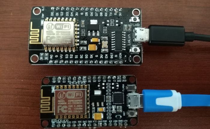
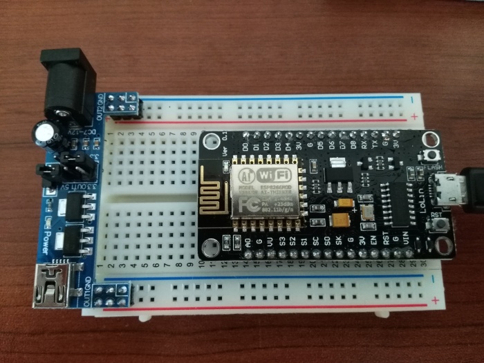
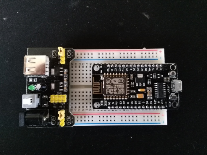
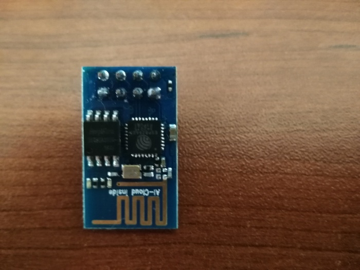
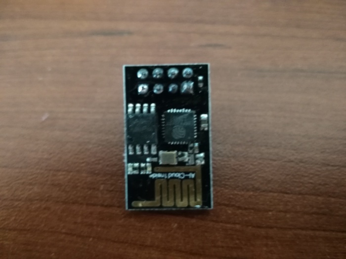
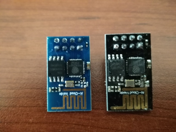
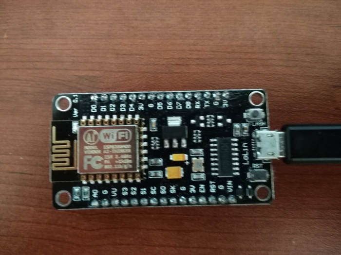
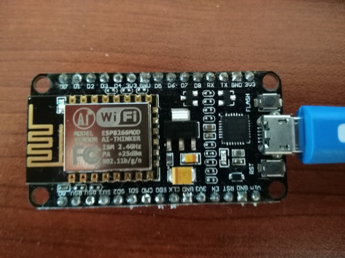
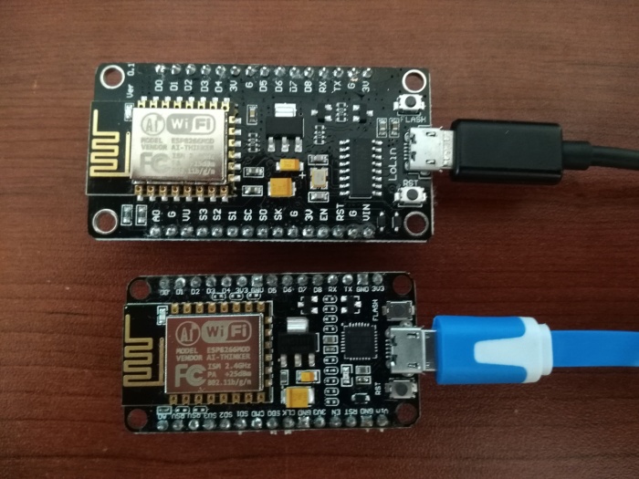
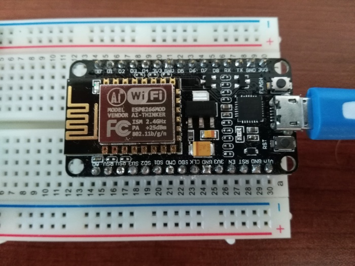
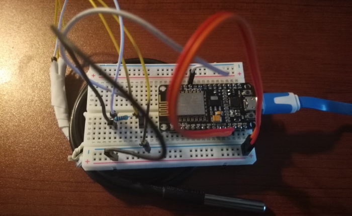
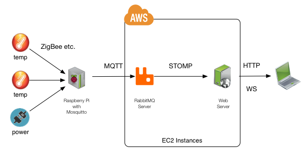
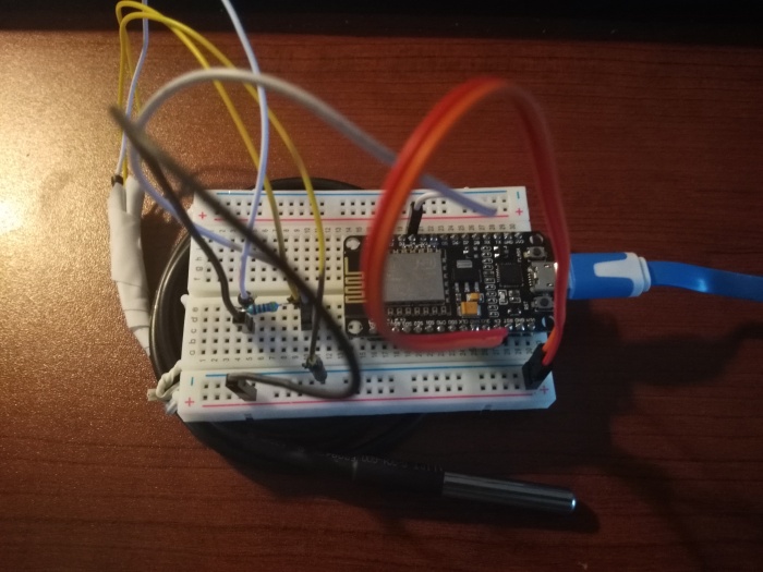
Okay done with theory. I have just installed Mosquitto on my Raspberry PI so in next post I would like to show you a bit more DIY base on ESP8266 sensors which we used previously. But if you haven’t do it then I am inviting you to read previous posts and get more familiar with ESP8266.

-> https://gettoknowthebob.wordpress.com/

Have a nice day!


12295299_1691497957737189_7709343665767663600_n

Github repository: https://goo.gl/ii9xsz

Be positive and stay calm!

Cheers,

Radek

Thingspeak – with Nodemcu (ESP8266) and DS18B20 thermometer sensor (part2)

Thingspeak – with Nodemcu (ESP8266) and DS18B20 thermometer sensor (part2)
Hi Readers,
Last post I wrote about Thingspeak – easy to use IoT platform (part1) where I hope I showed you why I really liked this platform. I invite you to read it before reading this post.
Today I would like to show you how to use your device (in my case it was Nodemcu and ESP8266) with thingspeak account. How to read temperature from DS18B20 sensor and upload it to right thingspeak channel field.

Account

First thing you need to do you need to create account on thingspeak.com.

Channels / device

Next thing you need to add new channel which could be your device or group of devices. Each channel have 8 fields which then you can use to store data from your device or devices. I have used one channel with one field where I am writing temperature values every 17 seconds (thingspeak is able to store data after 16s).
Chan1

Source code

I think there is not ESP6288 on supported list of devices but as they API is really easy to use we can use it to send data to ThingSpeak from any device which has internet connection.
Below I have added source code I have used on my Nodemcu (ESP8266-12E).
It read data from DS18B20 sensor then send it to thingspeak server. This way updates temperature value.

#include <Arduino.h>
#include <ESP8266WiFi.h>
#include <OneWire.h>
#include <DallasTemperature.h>

#define myPeriodic 15 // Seconds
#define ONE_WIRE_BUS 2 // DS18B20 on arduino pin2 corresponds to D4 on physical board

OneWire oneWire(ONE_WIRE_BUS);
DallasTemperature DS18B20(&oneWire);
WiFiClient client;

// replace with your channel’s thingspeak API key,
String apiKey = “B9HSYHJWRKYUILAA”;
const char* ssid = “ssid”;
const char* password = “password”;
const char* server = “api.thingspeak.com”;

void setup() {
Serial.begin(115200);
delay(10);

WiFi.begin(ssid, password);

Serial.println();
Serial.println();
Serial.print(“Connecting with “);
Serial.println(ssid);

WiFi.begin(ssid, password);

while (WiFi.status() != WL_CONNECTED) {
delay(500);
Serial.print(“.”);
}
Serial.println(“”);
Serial.println(“WiFi Connected”);
}

void loop() {
float temp;
DS18B20.requestTemperatures();
temp = DS18B20.getTempCByIndex(0);

if (client.connect(server,80)) {
String postStr = apiKey;
postStr +=”&field1=”;
postStr += String(temp);
postStr += “\r\n\r\n”;

client.print(“POST /update HTTP/1.1\n”);
client.print(“Host: api.thingspeak.com\n”);
client.print(“Connection: close\n”);
client.print(“X-THINGSPEAKAPIKEY: “+apiKey+”\n”);
client.print(“Content-Type: application/x-www-form-urlencoded\n”);
client.print(“Content-Length: “);
client.print(postStr.length());
client.print(“\n\n”);
client.print(postStr);

Serial.print(“Temperature: “);
Serial.println(temp);
}
client.stop();

delay(17000); // 17sec delay between updates
}

Source code file you can download from my gettoknowthebob github repository.

IMG_20160424_191928


Thingspeak & ESP8266Network channel

So this is how it looks after couple hours:

Chan2

Thingspeak also offers matlab code run tool which you can use to process all gained data in the way you need.

For example I have used example matlab code to calculate average temperature I have at home.

Matlab source code:

% Channel ID to read data from
readChannelID = 118421;
% Temperature Field ID
TemperatureFieldID = 1;

% Channel Read API Key
% If your channel is private, then enter the read API
% Key between the ” below:
readAPIKey = ‘BR6TVGG4CVSK9EID’;

temperature = thingSpeakRead(readChannelID, ‘Fields’, TemperatureFieldID, ‘NumMinutes’, 60, ‘ReadKey’, readAPIKey);
% Calculate the average temperature
avgTemperature = mean(temperature);
display(avgTemperature, ‘Average Temperature’)

And results:

Chan3


I hope it helped you. Give me a should in comments when you will have some questions.

Have a nice day!


1919035_1699744840245834_8385952294039797213_n


Github repository: https://goo.gl/ii9xsz

Be positive and stay calm!

Cheers,

Radek


Thingspeak – easy to use IoT platform (part1)

Thingspeak – easy to use IoT platform (part1)

Hi Readers,

Today I would like to introduce Thingspeak – open data platform for the IoT.

This platform allows you to simply collect data from your sensor then analyze it and trigger selected action:

CollectCollect – Send sensor data to the cloud.

AnalyzeAnalyze – Analyze and visualize your data.

ActAct – Trigger a reaction.

ThingSpeak Features

  • Real-time data collection and storage
  • MATLAB® analytics and visualizations
  • Alerts
  • Scheduling
  • Device communication
  • Open API
  • Geolocation data
  • Available on GitHub®


Personally I especially like ThingSpeak from its easy to use web panel and API. Last couple months I had many problems with ESP8266, nodemcu or some with domoticz configuration, uploading firmwares or testing tools and IDEs. I have spend many times hours on small problems which had resulting during tasks. And here I found ThingSpeak which I wanted to test. And you know what? In just 10minutes (really) I have created new account I have added new channel (device) and I have learned basic API example. Easy peazy, first time.

In my next blog post I will show you example source code I have created to upload data to thingspeak base on their API. Which again, wasn’t so hard.

Next thing I did base on temperature data I have tried to create basic Matlab project which was calculating average temperature in my home. Pretty easy. I will paste here Matlan source as and example.

% Channel ID to read data from
readChannelID = YourChannelId;
% Temperature Field ID
TemperatureFieldID = YourFieldId;

% Channel Read API Key
% If your channel is private, then enter the read API
% Key between the ” below:
readAPIKey = ”;

temperature = thingSpeakRead(readChannelID, ‘Fields’, TemperatureFieldID, ‘NumMinutes’, 60, ‘ReadKey’, readAPIKey);
% Calculate the average temperature
avgTemperature = mean(temperature);
display(avgTemperature, ‘Average Temperature’)

This is very useful feature. Last year we have rent new apartment. It is a lovely place but walls are really thin. When winter came it was really cold. I was heating apartment to 22-23 degrees in evening to have in the morning something close to 6-8 degrees which is really cold when you are getting up from under your linen. And today I see how useful it would be to store this data and next day see how fast temperature is decreasing. After that use this matlab code to get average and then easily program your central heating to be effective.

Of course we can buy thermometers which already do it. There is a lot of devices on the market but here you can do it in DIY manner based on 2$ nodemcu and spending time on something useful. Only benefits and all of it for almost free.

This is why I liked ThingSpeak so much. It is really cool platform for everybody.


12938301_1730343557185962_4719402062987769740_n


Github repository: https://goo.gl/ii9xsz

Be positive and stay calm!

Cheers,

Radek

Domoticz part 2 – configuration

Domoticz part 2 – configuration

Hi Readers,

In part 1 I have described domoticz installation process now let’s make the configuration.

First you need to connect to your domoticz server (windows, linux or IOS):

http://:8080/#/Hardware

First window you shall see:

DomoticzHomepage

If you this page this is good. Domoticz has successfully installed. Now you need to add Hardware (type of devices you have) and Devices (physical or virtual devices).

Let’s add first hardware, for me it was temperature sensor (Thermometer) as it is not any know device like e.g. TV but my own prototype board with nodemcu and DS18B20 temperature sensor.

DomoticzAddDummyDevice

After adding this hardware you will see this:

DomoticzDummyDeviceView

Probably you have noticed ‘Create Virtual Sensors’ button. When you will click it you will create virtual sensor which will be feeding data to domoticz server. For me it was my nodemcu DS18B20 sensor and power supply adapter.

IMG_20160515_202211

After that you should see in device section newly added device:

DomoticzDummyDeviceView2

What is important here is name ‘ThermometerDS18B20’ which we will need to set on our nodemcu/esp8266 with EspEasy on board (last week I have published post with tutorial how to install EspEasy on our ESP8266/nodemcu boards) or any other device configuration. As this is device ‘login’ mark is this name. Configuration of my nodemcu (+DS18B20) device which uses EspEasy:

DomoticzDummyTermometherView

My network (router) SSID and key, my controller (Raspberry PI) ip address and port number we have specified in my last post but default is 8080 and you can always use it.

EspEasyDeviceConfig

I have also configured my ‘device’ inside my device (nodemcu with ESPEasy) configuration. As you can see my device is DS18B20 sensor which I have connected on GPIO-2.

Untitled Sketch_bb

Have fun & good luck!

12924512_1729289440624707_7066086451943892407_n

Github repository: https://goo.gl/ii9xsz

Be positive and stay calm!

Cheers,

Radek

Domoticz part 1 – installation

Domoticz part 1 – installation

Hi Readers,

Domoticz has prepared it’s server version for all popular operation systems. Also installation process is very easy.


Windows

Windows installation is easy and I will not even try to tell you more about it as I am sure you know everything you need to do it.

Download: http://releases.domoticz.com/releases/release/domoticz_windows_x86.zip


Raspberry PI

Linux is also not so hard. I will put each command one by one with description when needed.

First you should do are three classic commands:

sudo apt-get update

sudo apt-get upgrade

sudo apt-get install build-essential -y

sudo reboot

Then you will need to install necessary libraries, you can probably have some of them (this is one line whole command which need to be copied to your terminal:

sudo apt-get install nano cmake libboost-dev libboost-thread-dev libboost-system-dev libsqlite3-dev curl libcurl4-openssl-dev libusb-dev zlib1g-dev libssl-dev git -y

sudo reboot

Let’s download and unpack domoticz for linux:

mkdir Domoticz

cd Domoticz

wget http://releases.domoticz.com/releases/release/domoticz_linux_armv7l.tgz

tar xvfz domoticz_linux_armv7l.tgz

When everything is ready now we can add it to our startup list:

sudo cp domoticz.sh /etc/init.d
sudo chmod +x /etc/init.d/domoticz.sh
sudo update-rc.d domoticz.sh defaults

Edit the startup script, esp. point DAEMON to the installation folder (but default settings should be enough):

sudo nano /etc/init.d/domoticz.sh
DAEMON=/home/YOURUSERNAME/domoticz/domoticz

If you want to use another web interface port change the ‘8080’ in: DAEMON_ARGS="$DAEMON_ARGS -www 8080" to your own port.


Control commands

You can now start/stop/restart domoticz with:
sudo /etc/init.d/domoticz.sh start to start Domoticz
sudo /etc/init.d/domoticz.sh stop to stop Domoticz
sudo /etc/init.d/domoticz.sh restart to restart Domoticz
sudo /etc/init.d/domoticz.sh status to check the status of Domoticz (running/not running)


Now you can start domoticz with:

sudo /etc/init.d/domoticz.sh start to start Domoticz

You should see:

pi@raspberrypi:~ $ sudo /etc/init.d/domoticz.sh start
[ ok ] Starting domoticz.sh (via systemctl): domoticz.service.


When domoticz have started then you can connect to it and make the configuration:

http://<ip_address&gt;:8080/#/Dashboard


But in my next post you will be able to find more about configuration is not hard but it wasn’t so obvious for me. Good luck!

12592264_1726425854244399_7763149214522641008_n


Github repository: https://goo.gl/ii9xsz

Be positive and stay calm!

Cheers,

Radek

ESPEasy installation on ESP8266 (preliminary to domoticz)

ESPEasy installation on ESP8266 (preliminary to domoticz)

Hi Readers,

Today I would like to show you how you can install ESPEasy on your ESP8266 modules. This is preliminary post to use ESP8266 with domoticz. On top of that last couple weeks I tried to prepare you and other readers to be able to connect different types of sensor to ESP8266. All of it together I hope in next weeks will result with very useful DIY home control system.

Okay, to the point. What you need?

  1. ESP8266 modules (I have tested it with ESP8266-01 blue and black and ESP8266-12E)
  2. If you will use ESP8266-01 then you will need some kind USB to Ttl converter I am using CP2102 USB 2.0 to Serial Converter but you can use any other.
  3. ESPEasy firmware which you need to upload to your ESP8266 modules

Connect USB convert to ESP8266-01

This slideshow requires JavaScript.

What is important you need to know you need to link GPIO0 with GND and CH_PD with 3.3V as this kind of connections will set ESP8266-01 in flashing mode. After flashing you will need to disconnect GPIO0 and reset board by e.g. disconnecting and connecting CH_PD.

Getting started with the ESP Easy takes a few basic steps. In most cases your ESP module comes with the AT firmware or the NodeMCU LUA firmware. We need to replace the existing firmware with the ESP Easy firmware (From domoticz)

You can download all firmware types as one package from it contains flash tool which we will use to upgrade ESP8266 modules with new firmware:

https://sourceforge.net/projects/espeasy/

After downloading and unpacking ESPEasy package you will see couple files:

  1. bin – firmware files
  2. esptool.exe – flashing application
  3. flash.cmd – basic windows script which will run flashing app with settings we will set

You will need to edit your flash.cmd file and customize it for you needs. Flash.cmd should looks similar to this:

@echo off
set /p comport= Comport (example 3, 4, ..) :
set /p fsize= Flash Size (example 512, 1024, 4096) :
set /p build= Build (example 71, 72, ..) :

echo Using com port: %comport%
echo Using bin file: ESPEasy_R%build%_%fsize%.bin

esptool.exe -vv -cd nodemcu -cb 115200 -cp COM%comport% -ca 0x00000 -cf ESPEasy_R%build%_%fsize%.bin

pause

To adjust it for you needs you need to choose comport, firmware file size and build version.

I will show you my settings hope it will help. For each settings I will quote I will invite you to create a new file (e.g. flash_esp7266_01_black.cmd) and copy paste script code.

ESP8266-01 (black)

My configuration:

Module – ESP8266-01 (black 1024kb)

Comport – COM11

Filename – ESPEasy_R78_1024.bin (1024 version as ESP8266-01 black has 1024 memory)

@echo off

esptool.exe -vv -cd nodemcu -cb 115200 -cp COM11 -ca 0x00000 -cf ESPEasy_R78_1024.bin

pause

ESP8266-01 (blue)

My configuration:

Module – ESP8266-01 (black 512kb)

Comport – COM11

Filename – ESPEasy_R78_512.bin (512 version as ESP8266-01 blue has 512 memory)

@echo off

esptool.exe -vv -cd nodemcu -cb 115200 -cp COM11 -ca 0x00000 -cf ESPEasy_R78_512.bin

pause

ESP8266-12E (nodemcu)

My configuration:

Module – ESP8266-12E (nodemcu)

Comport – COM8

Filename – ESPEasy_R78_4096.bin (4096version as ESP8266-12E (nodemcu) has 4096 memory)

@echo off

esptool.exe -vv -cd nodemcu -cb 115200 -cp COM8 -ca 0x00000 -cf ESPEasy_R78_4096.bin

pause

When you have created flash…cmd file then you need to run it and wait until you will see information that flashing has ended.

If it ended successful and you have restarted modules then you will be able to connect to module as first it creates Access point to which you can connect and configure it. As e.g. to connect to your domoticz server through you local router.

12190120_1687272744826377_2697381623180505437_n

Github repository: https://goo.gl/ii9xsz

Be positive and stay calm!

Cheers,

Radek

Touch controlled buzzer (Nodemcu ESP8266)

Touch controlled buzzer (Nodemcu ESP8266)

Hi Readers,

Today I would like to show you DIY doorbell or just hand controlled annoying buzzer.

What you need:

  1. Cheap buzzer which cost about 1-3 euro.
  2. Touch sensor another 3 euro
  3. Cables
  4. Nodemcu or any arduino board


Connections


TouchControlledBuzzer_bb
Fritzing project I have added to GetToKnowTheBob git repository


Source code (PlatformIO & Arduino)

int returnValue = 0;

void setup() {
Serial.begin(115200);
pinMode(2, INPUT);
pinMode(4, OUTPUT);
delay(1000);
}

void loop() {
returnValue = analogRead(2);
Serial.println(“Sensor value: ” + String(returnValue));
delay(100);
if(returnValue > 500)
analogWrite(4,1);
else
analogWrite(4,0);
}


Complete project

IMG_20160508_162349


This example is very practical. You can simply use it to other sensors. I have used it also with Passive infrared sensor – motion detector.

IMG_20160508_172557


This post is initial post for future projects I will publish on GetToKnowTheBob blog.

Have fun!


my-mouse-rikiki-wants-to-be-a-part-of-the-real-world__013


Github repository: https://goo.gl/ii9xsz

Be positive and stay calm!

Cheers,

Radek

PlatformIO IDE your IoT friend.

PlatformIO IDE your IoT friend.

Hi Readers,

Today I would like to show you PlatformIO IDE. It is easy to use and in my opinion much nicer and more sophisticated alternative to Arduino Studio. Maybe it is not so easy to use as it needs some configuration at first but it is a basic process that everybody can do. Also I have noticed that platformio is really working on improving whole environment.


What is the PlatformIO


platformio-logo-17fdc3bc


PlatformIO IDE is the next-generation integrated development environment for IoT:

Cross-platform build system without external dependencies to the OS software: 200+ embedded boards,15+ development platforms, 10+ frameworks

C/C++ Intelligent Code Completionand Smart Code Linter for rapid professional development

Multi-projects workflow with multiple panes and Themes support with dark and light colors

Built-in Terminal with PlatformIO CLI tool and powerful Serial Port Monitor

PlatformIO IDE is a IDE build on Atom “A hackable text editor” which you can find more about on their homepage : https://atom.io .

It supports number of boards and especially useful for us it supports all ESP8266 boards I know about. I am using it with my ESP6288-01 and Nodemcu ESP8266-12E boards.

Installation

What you need to do to install it? Just download platformio installation from: http://platformio.org/get-started and it is done. But if you will end-up with some errors which unfortunately I did twice on my laptop. Just reinstall it again it should help.

List of supported boards: http://platformio.org/boards


plotfio

Libraries

Probably from the begging you will miss some libraries but don’t be worry PlatformIO has hundreds libraries in their repository.

To find the right one you should run Library Manager (from menu) they console will popup. Then you need to type:

platformio lib search <name_of_missing_library>

platformio lib search 1-wire

After that you will see list of libraries which are consistent with your search.

PlatformioSearch

When you want to install one of found libraries you need to type:

platformio lib install <library_id>

platformio lib install 1


Configuration

Platformio has large number of possible settings we can customize. But most important is platformio.ini file which contains settings of your project.

Settings I am using for my Nodemcu are:

[env:nodemcuv2]
platform = espressif
framework = arduino
board = nodemcuv2
upload_speed = 115200
#upload_port = COM5


plotfi2o


Platformio.ini configuration: http://docs.platformio.org/en/latest/projectconf.html#upload-speed

You can find there much more settings you can choose it is a bit lecture bit it also mean that everybody will be well served by PlatformIO IDE.

Give it a try. I am sure you will like it as I did.


Github repository: https://goo.gl/ii9xsz

Be positive and stay calm!

Cheers,

Radek

Power supply modules and ESP8266 module types.

Power supply modules and ESP8266 module types.

Hi Readers,

Today I would like to share with you power supplies I am have tested and ESP8266 modules which I am currently using. I have done those tests as often when I was connecting one or another sensor to ESP8266 module it was loosing power and resetting itself.

Breadboard power supply modules

1) Breadboard power supply module

IMG_20160501_170231

This one I like the most. It fits well, doesn’t fell off easily. Can operate on DC 6V – 12V input and does 3.3V or 5V output. Has reset button also additional power pins which are usefull in most DIY projects. You can use e.g. 4 x AA or 4 x AAA batteries or 9V battery.

2) Breadboard power supply modules

IMG_20160501_170255

This is seconds breadboard power supply. It can be powered byt DC 7V to 12V. As a output has 3.3V or 5V. Has more common micro usb socket so could be powered up from any PC, laptop or power bank by any smartphone similar cable.

3) Additional elements

You can use external power supply, usb cable or any other type of power source. I have used batteries as they are cheap and portable.

IMG_20160501_170854IMG_20160501_170909IMG_20160501_171320IMG_20160501_170759IMG_20160501_170818IMG_20160501_170700IMG_20160501_110737

ESP8266 Modules

Modules I am using:

IMG_20160501_170455IMG_20160501_170503IMG_20160501_170513

Those are to basic and I think cheapest easy to use ESP8266 modules. You can simply find and order them from chine. They cost about 2$ per peace. Different between those is memory size blue modules has only 512kb where black has 1024kb.

IMG_20160501_170343IMG_20160501_170424IMG_20160501_170439IMG_20160501_170619IMG_20160501_170700

Those are nodemcu modules which has ESP12 modules. They are three version of it but V2 and V3 are most popular. I read that those modules are similar but even from hardware site there are similar their sizes are unfortunately different. V3 is just to big in my opinion as when installed on breadboard there is not holes left to connect anything to it. V2 is a les wide in compare to V3 and has 2 lines of wholes left when installed in breadboard. You can see it on attached pictures.

According to other types of ESP8266 modules. You can read more on esp8266 homepage under this like:

http://www.esp8266.com/wiki/doku.php?id=esp8266-module-family

1610038_1722052748015043_1288277534162828799_n

Github repository: https://goo.gl/ii9xsz

Be positive and stay calm!

Cheers,

Radek

Thermometer = Nodemcu ESP8266 + DS18B20

Thermometer = Nodemcu ESP8266 + DS18B20

Hi Readers,

Today I would like to show you how we can use our nodemcu as a simple thermometer.

What you need:

  1. Nodemcu (esp8266)
  2. DS18B20
  3. Arduino studio
  4. Serialport monitor (for example the one from Arduino studio)

You can also use:

  1. Breadboard
  2. Couple connectors
  3. 4.7k ohms resistor

How it should be connected?

Untitled Sketch_bb

As you can see on attached picture you need to first connect 3.3V and GND on your breadboard to edge breadboard. Then you simply should connect DS18B20 sensor legs to 3.3V and GND plus its DQ to Nodemcu D4 and also connect it by 4.7k ohm resistor to the 3.3V.

This is how it looked for me

IMG_20160424_191928

I am sure you have manage to connect everything so let’s do some coding.

I have created example code (based on ajaran source code) which you can build and upload by Arduino studio (I used it) and test and use device you have just created! If you haven’t noticed that you have just build basic and simple thermometer :). In example source code gathered temperate I am printing to the serial port. So you can use really any serial monitor to read current temperature.

#include
#include
#include

#define myPeriodic 15 // Seconds
#define ONE_WIRE_BUS 2 // DS18B20 on arduino pin2 corresponds to D4 on physical board

OneWire oneWire(ONE_WIRE_BUS);
DallasTemperature DS18B20(&oneWire);
float prevTemp = 0;
const char* MY_SSID = “ssid”;
const char* MY_PWD = “password”;
int sent = 0;
void setup() {
Serial.begin(115200);
}

void loop() {
float temp;
DS18B20.requestTemperatures();
temp = DS18B20.getTempCByIndex(0);
Serial.print(String(sent)+” Temperature: “);
Serial.println(temp);
sent++;
int count = myPeriodic;
while(count–)
delay(1000);
}

I have hope you enjoyed this post. I did!

12832321_1215052848518740_5770579544392527095_n

Github repository: https://goo.gl/ii9xsz

Be positive and stay calm!

Cheers,

Radek